Cantilever bridge
Bridge built using cantilevers
From Wikipedia, the free encyclopedia
A cantilever bridge is a bridge built using structures that project horizontally into space, supported on only one end (called cantilevers). For small footbridges, the cantilevers may be simple beams; however, large cantilever bridges designed to handle road or rail traffic use trusses built from structural steel, or box girders built from prestressed concrete.

The Pierre Pflimlin Bridge is a balanced cantilever made of concrete, shown here under construction. | |
| Span range | Medium |
|---|---|
| Material | Iron, structural steel, prestressed concrete |
| Movable | No |
| Design effort | Medium |
| Falsework required | Very little to none |
The steel truss cantilever bridge was a major engineering breakthrough when first put into practice, as it can span distances of over 1,500 feet (450 m), and can be more easily constructed at difficult crossings by virtue of using little or no falsework.
Origins

Engineers in the 19th century understood that a bridge continuous across multiple supports would distribute the loads among them. This would result in lower stresses in the girder or truss and meant that longer spans could be built.[1]: 57, 190 Several 19th-century engineers patented continuous bridges with hinge points mid-span.[2]: 75, 79 The use of a hinge in the multi-span system presented the advantages of a statically determinate system[3] and of a bridge that could handle differential settlement of the foundations.[1]: 190 Engineers could more easily calculate the forces and stresses with a hinge in the girder.
Heinrich Gerber was one of the engineers to obtain a patent for a hinged girder (1866) and is recognized as the first to build one.[2]: 79 Located in Germany, the Hassfurt Bridge over the Main river in Germany with a central span of 124 feet (38 metres) was completed in 1867 and is recognized as the first modern cantilever bridge.[3]: par. 2

The High Bridge of Kentucky by C. Shaler Smith (1877), the Niagara Cantilever Bridge by Charles Conrad Schneider (1883) and the Poughkeepsie Bridge by John Francis O'Rourke and Pomeroy P. Dickinson (1889) were all important early uses of the cantilever design.[3]: par. 3, 5 The Kentucky River Bridge spanned a gorge 275 feet (84 metres) deep and took full advantage of the fact that falsework, or temporary support, is not needed for the main span of a cantilever bridge.[3]: par. 3
The Forth Bridge is a notable example of an early cantilever bridge. This bridge held the record for longest span in the world for twenty-nine years until it was surpassed by the Quebec Bridge. The engineers responsible for the bridge, Sir Benjamin Baker and Sir John Fowler, demonstrated the structural principles of the suspended span cantilever by sitting in chairs and supporting their colleague, Kaichi Watanabe, in between them, using just their arms and wooden poles. The suspended span, where Watanabe sits, is in the center. The wooden poles resist the compression of the lower chord, while the outstretched arms support the tension of the upper chord. The placement of the brick counterweights demonstrates the action of the outer foundations.[3]: par. 6
Function
Cantilever Bridge.—A structure at least one portion of which acts as an anchorage for sustaining another portion which extends beyond the supporting pier.
— John Alexander Low Waddell, Bridge Engineering[4]
A simple cantilever span is formed by two cantilever arms extending from opposite sides of an obstacle to be crossed, meeting at the center. In a common variant, the suspended span, the cantilever arms do not meet in the center; instead, they support a central truss bridge which rests on the ends of the cantilever arms. The suspended span may be built off-site and lifted into place, or constructed in place using special travelling supports.

A common way to construct steel truss and prestressed concrete cantilever spans is to counterbalance each cantilever arm with another cantilever arm projecting the opposite direction, forming a balanced cantilever; when they attach to a solid foundation, the counterbalancing arms are called anchor arms. Thus, in a bridge built on two foundation piers, there are four cantilever arms: two which span the obstacle, and two anchor arms that extend away from the obstacle. Because of the need for more strength at the balanced cantilever's supports, the bridge superstructure often[citation needed] takes the form of towers above the foundation piers. The Commodore Barry Bridge is an example of this type of cantilever bridge.
Steel truss cantilevers support loads by tension of the upper members and compression of the lower ones. Commonly, the structure distributes the tension via the anchor arms to the outermost supports, while the compression is carried to the foundations beneath the central towers. Many truss cantilever bridges use pinned joints and are therefore statically determinate with no members carrying mixed loads.
Prestressed concrete balanced cantilever bridges are often built using segmental construction.
Construction methods
Some steel arch bridges (such as the Navajo Bridge) are built using pure cantilever spans from each side, with neither falsework below nor temporary supporting towers and cables above. These are then joined with a pin, usually after forcing the union point apart, and when jacks are removed and the bridge decking is added the bridge becomes a truss arch bridge. Such unsupported construction is only possible where appropriate rock is available to support the tension in the upper chord of the span during construction, usually limiting this method to the spanning of narrow canyons.
Another way to build a cantilever bridge is to have a stiff material and make a long plate out of said material, and place it across a gap, and add weights on both sides. These are called counterweights. This is a true counterweight bridge. Also see cantilever bridge

List by length
World's longest cantilever bridges (by longest span):[5]
| No | Bridge | Location | Country | Date | Length |
|---|---|---|---|---|---|
| 1 | Quebec Bridge | Quebec | Canada | 1919 | 1,800 ft (549 m) |
| 2 | Forth Bridge | Firth of Forth | Scotland | 1890 | 1,710 ft (521 m) × 2 |
| 3 | Minato Bridge | Osaka | Japan | 1973 | 1,673 ft (510 m) |
| 4 | Commodore Barry Bridge | Chester, Pennsylvania | United States | 1974 | 1,644 ft (501 m) |
| 5 | Crescent City Connection (dual spans) | New Orleans, Louisiana | United States | 1958 & 1988 | 1,575 ft (480 m) |
| 6 | Howrah Bridge | Kolkata, West Bengal | India | 1943 | 1,500 ft (457 m) |
| 7 | Gramercy Bridge | Gramercy, Louisiana | United States | 1995 | 1,460 ft (445 m) |
| 8 | Tokyo Gate Bridge | Tokyo | Japan | 2012 | 1,443 ft (440 m) |
| 9 | J. C. Van Horne Bridge | Campbellton, New Brunswick & Pointe-à-la-Croix, Quebec | Canada | 1961 | 1,247 ft (380 m) |
| 10 | Horace Wilkinson Bridge | Baton Rouge, Louisiana | United States | 1968 | 1,235 ft (376 m) |
| 11 | Tappan Zee Bridge | South Nyack, New York & Tarrytown, New York | United States | 1955 | 1,212 ft (369 m) |
| 12 | Lewis and Clark Bridge | Longview, Washington & Rainier, Oregon | United States | 1930 | 1,200 ft (366 m) |
Examples
 The Quebec Bridge is of the general structure described above.
 The Vejle Fjord Bridge is a concrete bridge built using the balanced cantilever method.
 Former eastern span of the San Francisco–Oakland Bay Bridge
 The Forth Bridge with its three double cantilevers.
 Original 1938 span of the Blue Water Bridge
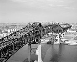
 Vrengen Bridge, a concrete bridge.


.jpg)

